Q69
Roller Conveyor
Steel plates, profiles and fabricated structures
Explore machine
Home / Machines / Abrasive Recovery System for Roller Conveyor Shot Blasting Lines
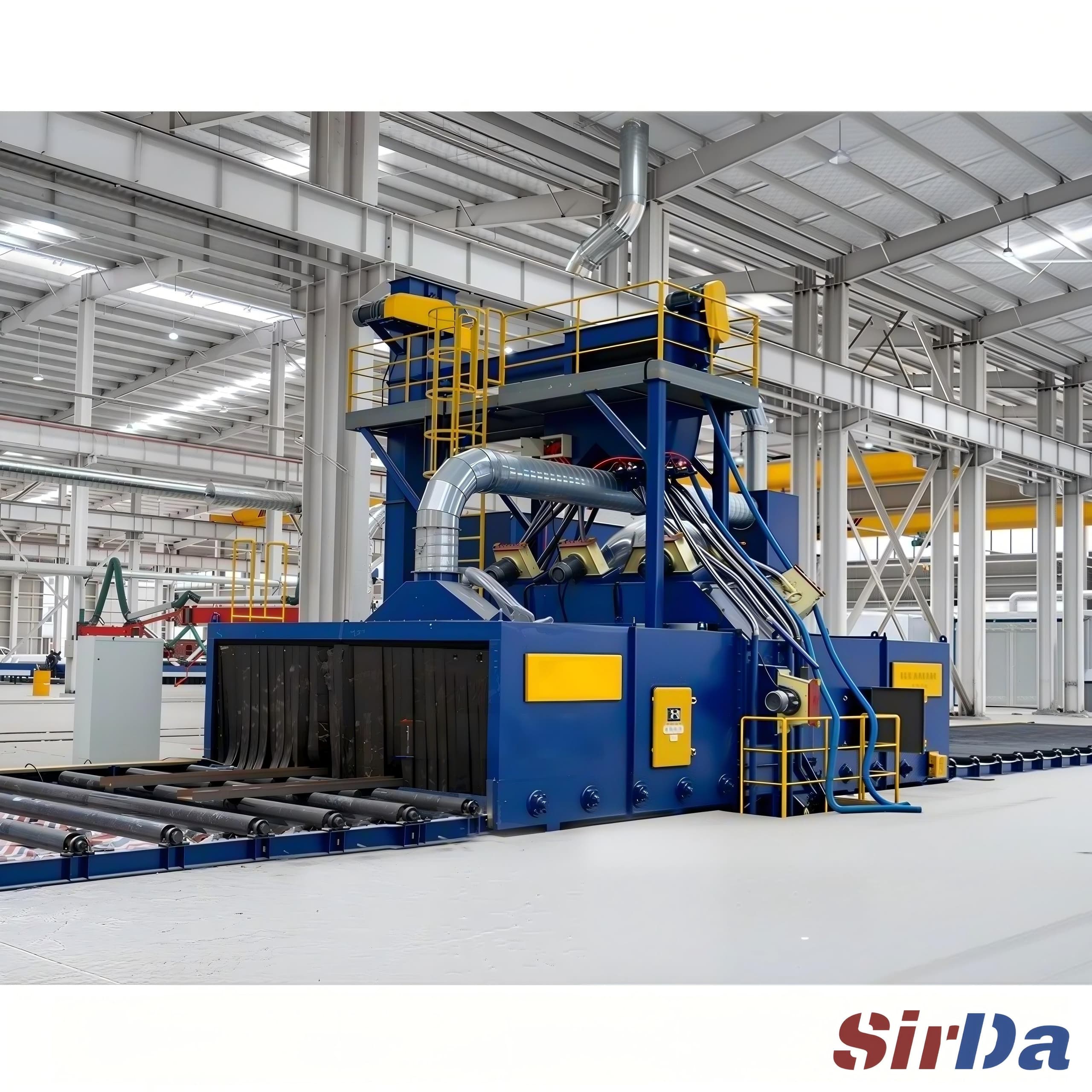
An abrasive recovery system for continuous roller conveyor shot blasting lines closes the loop between the blast chamber and the media supply, so spent abrasive and workpiece debris are separated before the media returns to the wheels. Recovery quality determines consumable cost, wheel maintenance intervals and how consistently the line holds a given surface standard.
Read product details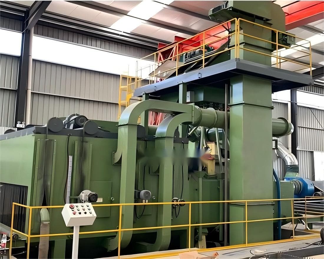
In a continuous roller conveyor shot blasting line, the media supply looks like the consumable detail and behaves like the cost centre. Steel shot or cut wire is thrown at the workpiece by blast wheels, breaks down into smaller particles as it works, and picks up two unwanted populations on the way: fractured media too small to be useful, and debris knocked off the workpiece itself. Whatever is not separated before the media goes back to the wheels comes back into the chamber.
That is what an abrasive recovery system is for. It sits between the blast chamber and the media supply and performs one job: separate the three populations so that only usable media returns to the blast wheels.
A blast wheel does not clean media, it consumes it. Every impact removes a small amount of the particle surface, and the particle travels from the wheel, through the chamber, along the recovery path and back to the wheel. If the recovery path cannot sort by size and by density, the cycle that was supposed to preserve the media slowly destroys it.
Three failure modes follow directly from that, and they are worth separating because they look similar on the shop floor and have completely different causes.
None of these show up as one dramatic event. They accumulate, which is why the recovery system has to be specified and inspected as part of the machine rather than treated as an accessory to add later.
The path from the chamber back to the media hopper is a short sequence of separations, and each step removes a different population. Getting the order right matters more than getting any single step fancy.
There is a practical consequence to this order that is easy to miss when a line is specified part by part. Each stage only works if the material reaching it is in a predictable condition. A separator that is fed with debris-laden media behaves differently from the same separator fed with clean media, and the setting that was correct during commissioning is no longer correct once the line has processed production work. Recovery performance is therefore a maintained condition, not a fixed specification.
Abrasive is bought by weight, and the useful fraction of that weight is determined by what the recovery system keeps and what it discards. A recovery system that returns too much fine material will look efficient on paper, because more media returns to the hopper, and will in practice consume media faster, because fine particles do not clean and do get used up. A system that discards too aggressively has the opposite problem: the recovered volume looks poor and the make-up media cost rises.
The same mechanism shows up in maintenance. Media that has been allowed to break down travels as a mixture rather than as a uniform stream, and a mixed stream changes how the flow behaves through the recovery path, how the wear liners erode, and how quickly the wheel casing wears at the blade roots. The blast wheel is the most expensive wear part on the line, and its life is set by the media condition arriving at it, not by the hours on the clock.
There is a third effect that is easy to overlook. The dust load in the chamber is largely a function of what the recovery path is allowed to pass downstream. When fines and debris are being carried into the filter instead of being separated out, the filter works harder, the pressure drop across it rises, and the extraction fan has to be run harder to hold the same negative pressure in the chamber. Recovery performance is therefore also a dust-collection cost, and it connects directly to how the extraction side is specified.
An abrasive recovery system integrated with the machine is the right configuration when the line runs a continuous flow of parts through a blast chamber and the same media has to be reused across many parts. That is the normal case for a roller conveyor line: the media budget only works if the recovered fraction is large enough to keep the make-up requirement down.
The configuration matters less when the volume of work is small, the parts are few and heavy, or the media itself is short-lived in the application. A batch machine handling a handful of large castings once a week does not need a continuous recovery loop to be economical, and specifying one adds capital and maintenance for very little return. The same applies to applications where the workpiece itself is fragile enough that the debris load is the dominant consideration, because there the recovery path has to be conservatively open, and a large recovered fraction cannot be assumed.
For mixed production, where a line handles both small parts in volume and occasional large items, the recovery system needs to be specified for the case that actually stresses it. A separator that handles the fine fraction well can still choke on the large workpiece debris that comes with heavy parts, and that is exactly where the difference between a designed recovery path and an improvised one shows up.
Every configuration below is reviewed against the actual production requirement rather than fixed in advance.
Share a photo or drawing, material, maximum dimensions and expected output. These details help us review a suitable configuration.
Send project requirementsQ69
Steel plates, profiles and fabricated structures
Explore machine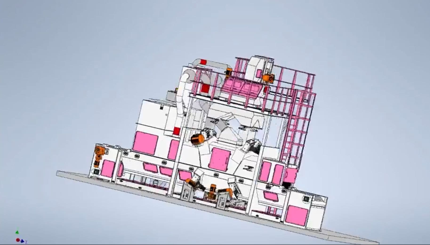
Continuous flow
Automatic mesh belt shot blasting machine for high-volume small steel parts such as cuplock scaffolding couplers and paver components. The continuous in/out flow removes the per-batch load/unload dwell that caps batch machines, so throughput tracks belt speed instead of batch count.
Explore machine
Continuous flow
A continuous through-type shot blasting line cleans structural sections, tubes and plates while they keep moving. This page explains how blast wheel placement, media recycling and dust routing are configured around the workpiece cross-section.
Explore machine